
 English
 русский
 Español
 Deutsch
 عربى
 italiano
 中文
A digital rotameter air flow meter keeps the dependable float-and-tube principle that plant engineers already trust, then makes the reading useful beyond the panel. The practical question is what the digital layer actually changes, and what you should verify before ordering.
Most instrument engineers can picture the same scene. A skid-mounted air system carries three or four glass rotameters on a panel, showing purge air, seal air, and a compressor bypass. To log the values, an operator walks up, squints at the scale, and writes the numbers into a sheet. When a diaphragm fails or a valve drifts, the first hint is often a process fluctuation, not a meter reading. A digital rotameter air flow meter exists to close exactly that gap.
The conclusion up front: for clean, dry air at typical plant pressures below 1.0 MPa and temperatures below 100 °C, a variable-area meter with an integrated electronic output is usually the most economical way to secure a local reading, a repeatable 4–20 mA signal, and a low maintenance load in one body.
What the Digital Label Actually Means
A rotameter is a variable-area flow meter. A float sits in a slightly tapered tube, and the rising stream lifts the float until the annular gap around it passes exactly the volumetric rate. The float height is the measurement. What makes the meter digital is the sensing layer wrapped around that simple mechanism.
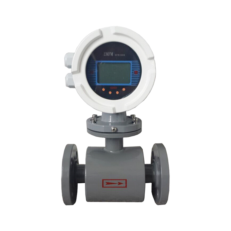
In industrial products you typically meet three arrangements: a magnetic float that drives an external follower, a position pickup such as an inductive or Hall-effect sensor, and a reed-switch chain that generates pulse or switch signals. Transmitter versions convert the float position into an industry-standard 4–20 mA output, or pulse for totalizing, so the value can travel to a PLC, DCS, or historian. The tube and scale stay visible, so an operator can still verify the flow with their own eyes.
| Configuration | What you get | Typical use |
|---|---|---|
| Local indication only | Float and scale, no power required | Visual checks and panel display |
| Limit alarm switch | One or two switching contacts | Low-flow and high-flow warnings |
| Transmitter | 4–20 mA, pulse, or digital protocol | PLC/DCS integration, logging, remote reading |
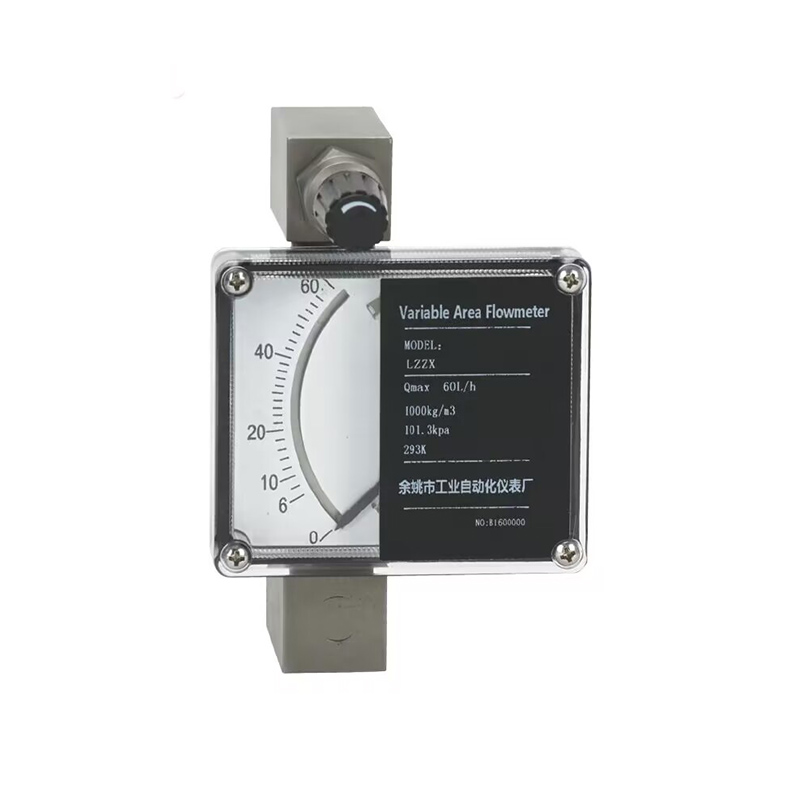
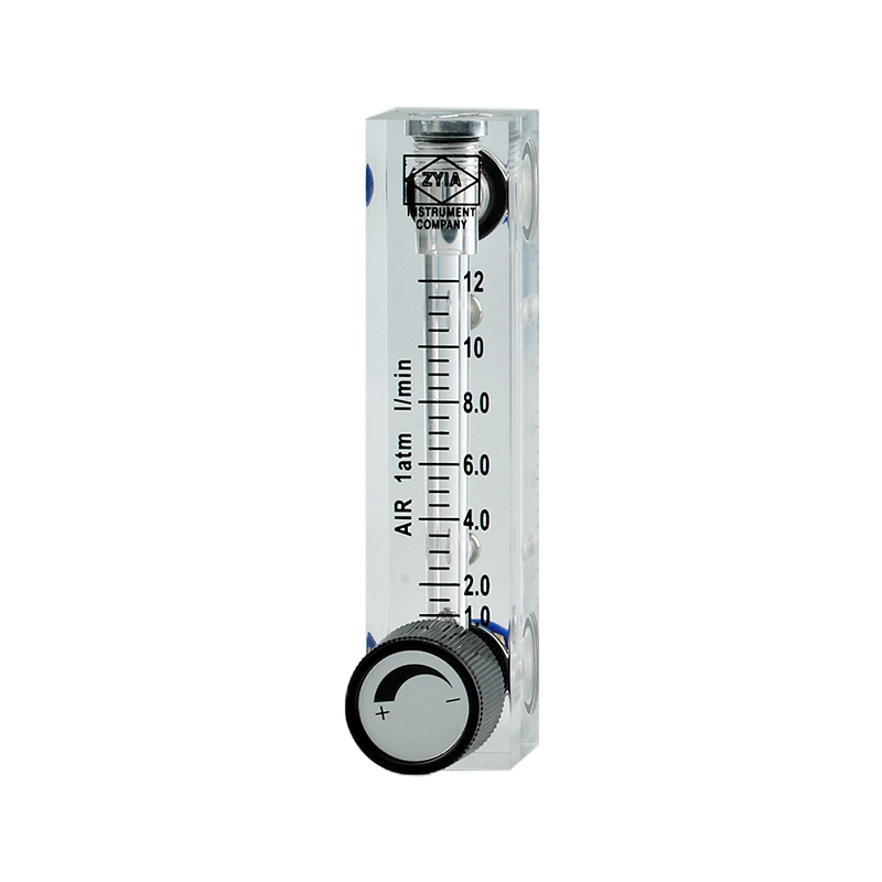
When the service is too hot or too pressurized for a glass tube, the metal-tube version with an integrated transmitter becomes the standard answer.
The float position is converted locally to 4–20 mA, the scale remains readable on site, and the control room sees the same value at every moment.
What Digital Output Improves, and What It Does Not
The gains are real
The biggest improvement is repeatability. Reading a float against a printed scale involves angle, parallax, and personal judgement; a position sensor removes nearly all of that variation, so the same flow produces the same output every time. Alarms respond faster, trends become visible, and a maintenance team can spot a slowly closing filter or a leaking bypass before the process complains. That capability sits at the center of the trend toward data-driven flow monitoring in industrial plants , where even simple meters are expected to talk to the system rather than wait for a walk-by.
The limitations stay the same
The electronic layer does not change the operating principle, so it does not change the accuracy class of the float meter. A typical glass-tube rotameter works in the region of ±2.5% of full scale; metal-tube versions can reach roughly ±1.6% with careful calibration. Transmitting the value digitally removes reading error and adds repeatability, but it does not convert a variable-area meter into a mass-flow device or a fiscal-grade instrument.
Selecting a Digital Rotameter for Air: Material, Range, and Output
Selection begins with the medium, not with the electronics. Air is uncomplicated in terms of material compatibility, but pressure and temperature quickly decide which tube construction is allowed.
| Tube material | Indicative pressure | Indicative temperature | Best suited for |
|---|---|---|---|
| Acrylic | 0.5–0.7 MPa typical | 40–60 °C typical | Low-pressure gas, analyzer panels, visual display |
| Glass | 1.0–1.6 MPa typical | 100–150 °C typical | General plant air, water, chemical compatibility |
| Metal | Model-dependent, above 1.6 MPa | Up to 200 °C typical | Hot, high-pressure, or aggressive services |
After the material, work through the output and range decisions:
- State the reference conditions, meaning the real working pressure and temperature at the installation point.
- Convert the normal and maximum flow into those conditions, not into standard conditions by default.
- Choose the output: alarm contacts, 4–20 mA, pulse, or a combination.
- Select the connection, whether thread, flange, triclamp, or panel configuration.
- Verify that a vertical straight run exists for the planned orientation.
A reliable rule is to size the scale so that normal operation sits between 40 and 70 percent of full scale. That leaves headroom for surges and keeps the float in the most linear part of the tube.
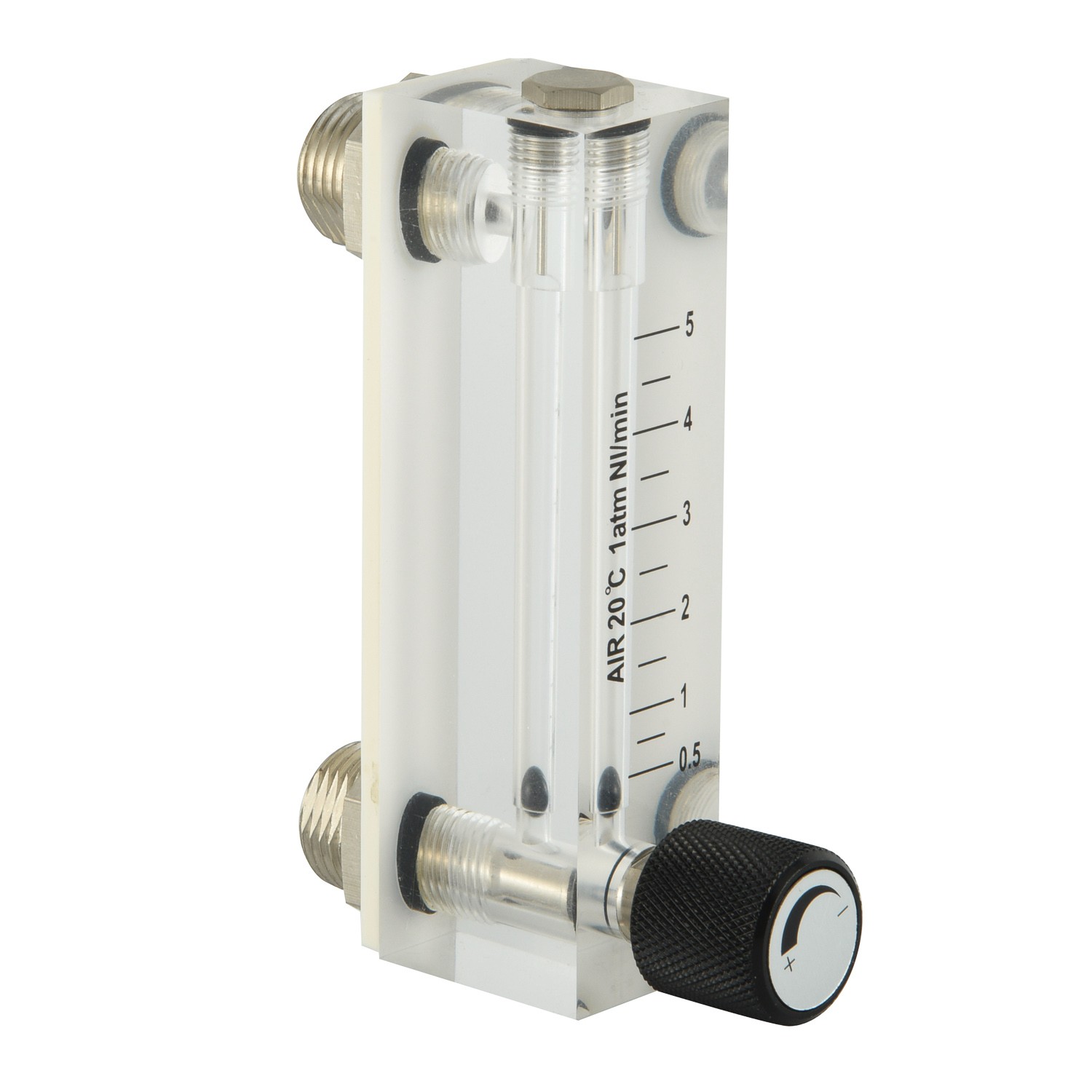
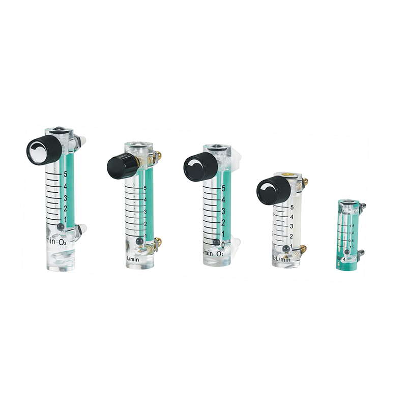
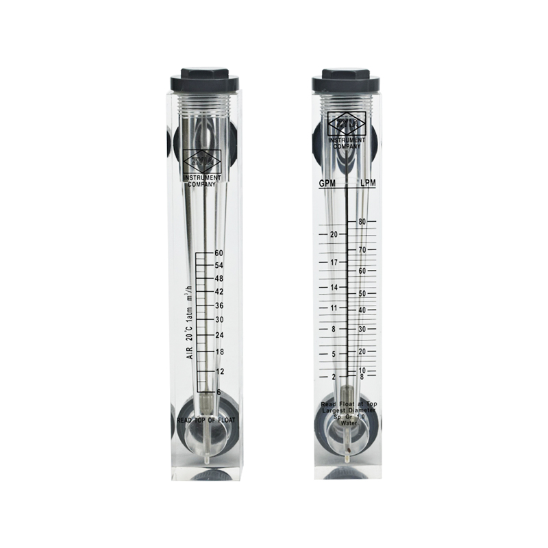
For low-pressure argon or CO2 streams on analyzer panels, an acrylic rotameter remains a sensible, low-cost choice.
The gas is clean, the pressure is low, and the scale is meant for an operator's eye as much as for a signal.
Air Calibration and Reference Conditions Matter More Than Any Chip
A rotameter is a volumetric instrument. Its scale is valid for a specific gas at a specific density, which in practice means one pressure and one temperature. If a meter was scaled for air at 101.325 kPa and 20 °C and then installed in a 0.4 MPa line without correction, the float will sit considerably higher than the true volumetric flow through the line.
The practical consequence is that the engineering specification sheet, not the tube, decides whether the meter works. The manufacturer needs the gas composition, the working pressure, the working temperature, and the desired flow units, whether m³/h at working conditions or Nm³/h, to calibrate the scale and set the transmitter span.
A flow meter is specified for one gas at one condition. Everything else is a correction, not an assumption.
Installation and Care That Keep the Reading Honest
Digital output removes the need for someone to read the scale, but it does not remove the mechanical requirements. A variable-area meter must be installed vertically, with flow entering from below, or the float has no defined relationship with the flow rate.
Give the meter a straight, unobstructed run. A few diameters of straight pipe upstream are usually sufficient, but avoid mounting directly after an elbow, a partially closed valve, or a blower discharge. In air service the typical disturbances are pulsation and vibration; both make the float oscillate and turn a clean reading into noise for the control loop.
Maintenance stays modest but real, and the material decides the routine:
- Acrylic tubes scratch easily, so clean with a soft cloth and a neutral detergent.
- Glass tubes demand protection from mechanical shock, though they handle chemical media well.
- Metal tubes tolerate the harshest conditions but should still be inspected for deposits.
Watch for oily or humid air that deposits on the tube wall, because a sticky float gradually loses repeatability before the error becomes obvious.
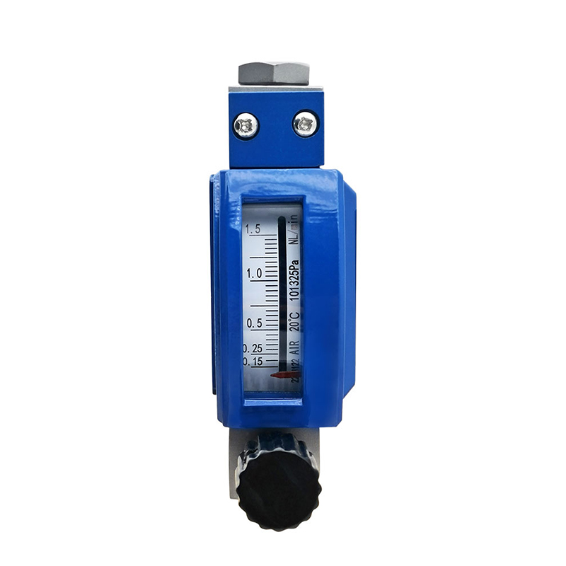
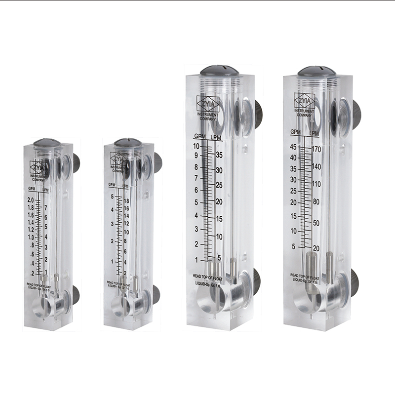
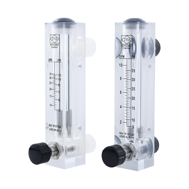
For panel-mounted instrument air or small sampling lines, the compact scaled glass-tube meters are the workhorses.
Their low flow ranges and visible floats make them easy to verify at a glance, and they accept limit or signal options when the panel must be monitored remotely.
Digital Rotameter, or a Different Technology?
Once you accept that the system needs a signal rather than a sight glass, the real decision is between technologies.
| Technology | Output | Typical accuracy | Strength | Main caution |
|---|---|---|---|---|
| Rotameter transmitter | 4–20 mA, pulse | ±1.6–2.5% full scale | Local reading, low cost, serviceable | Reference conditions affect reading |
| Thermal mass | 4–20 mA mass flow | ±1–2% | Compressed air energy accounting | Sensitive to dirt and wet gas |
| Vortex shedding | Frequency to 4–20 mA | ±1–1.5% | Wide ranges, steam and gas | Needs straight pipe, low flow limits |
| Orifice plate DP | 4–20 mA | ±2–3% | Simple, harsh conditions | Turndown, impulse line maintenance |
The balance is clear. If the goal is a plant-wide compressed-air energy audit, a thermal mass meter is the standard tool. If the goal is per-line rate indication with an alarm or a 4–20 mA signal, reasonable accuracy, visible local verification, and a sensible price, the digital rotameter remains the pragmatic choice.
Total cost of ownership reinforces the argument. Rotameters have no capillaries to block, no impulse lines to leak, and no ultrasonic transducers to fail. The float and tube are open to inspection. For clean air, that simplicity beats a more complex meter's specification sheet in the majority of routine duties.
The Bottom Line
Choose a digital rotameter air flow meter when the gas is clean, the pressure and temperature sit inside the chosen tube material's envelope, and you want a visible local reading plus a dependable electronic signal for your monitoring system. Define the reference conditions, size the scale around the normal operating point, confirm the output type, install the meter vertically, and keep the tube clean.
A supplier with the appropriate metrology license and quality system, one that publishes its certificates and factory records openly, will document the calibration conditions rather than leave them to chance. That documentation is the quiet difference between a meter that looks right and a meter that is right.